Introduction
Space engineering is one of the most technically demanding fields in modern engineering. Designing a mission that travels beyond Earth requires the integration of orbital mechanics, spacecraft systems, launch vehicles, flight dynamics, telemetry, simulation, geographic information, engineering data, and mission operations.
Students, researchers, educators, aerospace enthusiasts, engineers, and software developers often need multiple tools to explore these different areas. A single application may focus on orbital calculations, another on telemetry, another on GIS, and another on simulation.
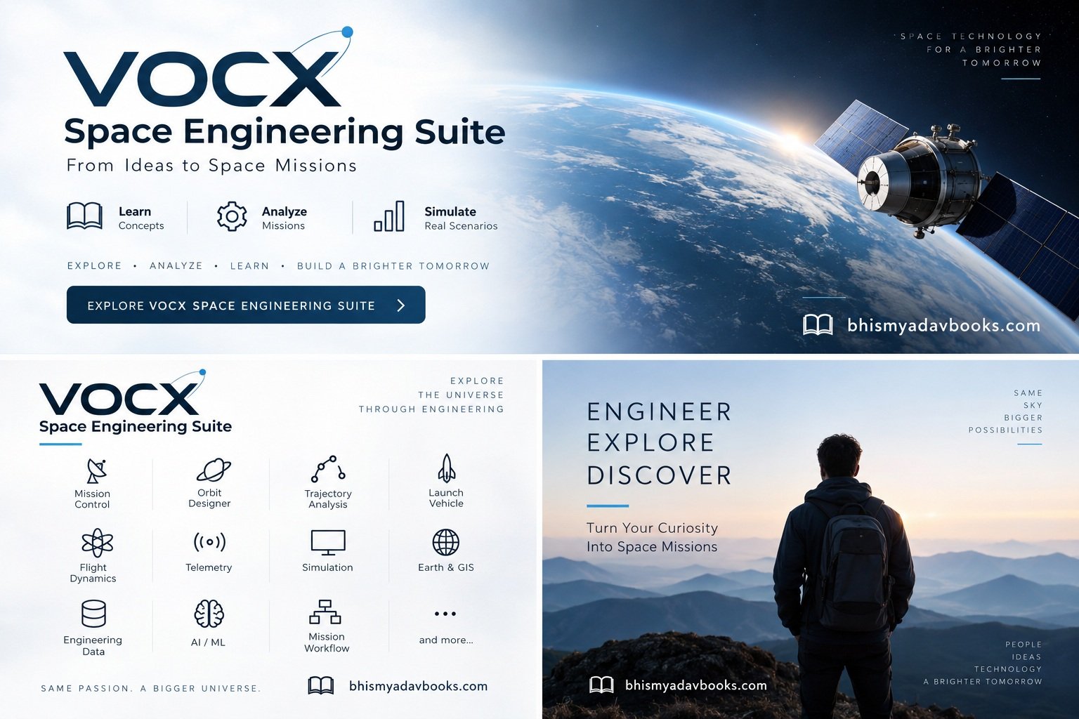
VOCX Space Engineering Suite is designed around the idea of bringing many of these space-engineering functions together in one integrated software environment.
We have some amazing books at our Shop page you may want to buy.
Visit Vocx Space Engineering Suite v1.0 Product page
The suite provides a collection of modules covering areas such as:
- Mission Control
- Mission Workflow
- Orbit Designer
- Hohmann Transfer
- Bi-Elliptic Transfer
- Hyperbolic / Escape
- Sphere of Influence
- Lambert Transfer
- Patched-Conic Transfer
- Launch Vehicle
- Flight Dynamics
- Telemetry
- Simulation
- Earth & GIS
- Engineering Data
Instead of treating these topics as completely separate subjects, VOCX Space Engineering Suite provides an environment where they can be studied and used as interconnected parts of a broader space mission.
This makes the software particularly useful as an educational, engineering, simulation, and mission-analysis platform.
Table of Contents
VOCX Space Engineering Suite: A Complete Platform for Space Mission Design and Engineering
What Is VOCX Space Engineering Suite?
VOCX Space Engineering Suite is a space-engineering software platform developed to bring important concepts from orbital mechanics, mission planning, spacecraft operations, simulation, and engineering analysis into one application environment.
A typical space mission involves many interconnected stages.
A simplified mission might look like this:
Mission Planning → Launch → Orbit Insertion → Orbit Operations → Maneuver → Tracking → Telemetry → Simulation → Analysis
Each stage requires different types of information.
For example, mission planning may require an understanding of objectives and mission phases. Orbit design requires orbital mechanics. Launch analysis requires launch vehicle information. Spacecraft operations require telemetry and flight dynamics. Geographic applications require Earth and GIS data.
VOCX Space Engineering Suite is organized around these different engineering requirements.
The goal is not simply to provide individual calculators. Instead, the broader concept is to create an environment in which users can explore how different space-engineering disciplines interact.
Why Space Engineering Software Is Important
Modern space missions depend heavily on software.
From a small educational satellite to a large interplanetary mission, software is involved in almost every stage.
Software can be used for:
- Mission planning
- Orbit determination
- Trajectory analysis
- Maneuver planning
- Launch analysis
- Spacecraft operations
- Telemetry monitoring
- Simulation
- Ground-station operations
- Geographic analysis
- Engineering calculations
- Data processing
- Artificial intelligence
- Machine learning
For students, understanding these software concepts can also provide a bridge between theoretical knowledge and practical engineering.
A textbook can explain the mathematical equation for orbital velocity.
A software environment can allow a learner to explore how changing altitude affects velocity.
That difference is important.
Instead of only reading:
v = √(μ/r)
a learner can change the orbital radius and observe how the calculated velocity changes.
This type of interaction can make complex engineering concepts easier to understand.
Major Modules of VOCX Space Engineering Suite
VOCX Space Engineering Suite contains a range of modules designed around different areas of space engineering.
The modules can be broadly divided into several categories:
Mission Operations
- Mission Control
- Mission Workflow
Orbital Mechanics
- Orbit Designer
- Hohmann Transfer
- Bi-Elliptic Transfer
- Hyperbolic / Escape
- Sphere of Influence
- Lambert Transfer
- Patched-Conic Transfer
Vehicle and Spacecraft Engineering
- Launch Vehicle
- Flight Dynamics
- Telemetry
- Engineering Data
Simulation and Earth Applications
- Simulation
- Earth & GIS
Advanced Computing
Each module addresses a different engineering problem while contributing to the overall space-mission workflow.
1. Mission Control
Mission Control is one of the central concepts in any space mission.
A spacecraft may be thousands or millions of kilometers away from Earth, but engineers and operators must continuously understand its condition and mission status.
A mission-control environment can bring together information such as:
- Mission status
- Spacecraft status
- Current mission phase
- Orbital information
- Telemetry
- Alerts
- Commands
- Flight parameters
- Events
- Communication status
Within VOCX Space Engineering Suite, the Mission Control concept provides a centralized environment for understanding mission operations.
For educational purposes, a mission-control module can also help users understand how different engineering subsystems contribute to mission operations.
For example, consider a spacecraft in Earth orbit.
The operator may need to understand:
Where is the spacecraft?
What orbit is it currently following?
What is its velocity?
What mission phase is active?
Is telemetry being received?
Is a maneuver scheduled?
These questions connect multiple areas of space engineering.
Mission Control therefore acts as an important connection between mission planning, orbital mechanics, telemetry, and spacecraft operations.
2. Mission Workflow
Space missions are not simply collections of independent calculations.
They follow a sequence.
A mission may begin with an initial concept and progress through:
- Mission objectives
- Mission requirements
- Orbit selection
- Launch planning
- Orbit insertion
- Orbit operations
- Maneuver planning
- Data collection
- Mission analysis
- End-of-mission operations
The Mission Workflow module is intended to organize this type of mission progression.
A workflow-oriented approach can help users understand how engineering activities are connected.
For students, this is particularly useful because space engineering can initially appear overwhelming.
There are equations, coordinate systems, spacecraft systems, launch vehicles, orbital transfers, telemetry, simulations, and geographic considerations.
A workflow provides structure.
Instead of approaching these subjects randomly, the learner can think in terms of a complete mission.
Understanding Mission Phases
A spacecraft mission can be divided into different phases depending on the mission.
For example:
Phase 1 — Mission Preparation
Mission requirements and objectives are defined.
Phase 2 — Launch
The launch vehicle carries the spacecraft toward its target trajectory.
Phase 3 — Orbit Insertion
The spacecraft reaches its intended initial orbit.
Phase 4 — Commissioning
Spacecraft systems are checked and configured.
Phase 5 — Operational Mission
The spacecraft performs its primary mission.
Phase 6 — Maneuvers
Orbital corrections or planned trajectory changes may be performed.
Phase 7 — Data Operations
The spacecraft collects and transmits mission data.
Phase 8 — End of Mission
The spacecraft may be deorbited, transferred to another orbit, or otherwise retired according to mission requirements.
Understanding these phases helps connect the different VOCX Space Engineering Suite modules.
3. Orbit Designer
Orbit design is fundamental to space missions.
A spacecraft’s orbit determines many aspects of its mission.
For example, the orbit influences:
- Orbital period
- Velocity
- Coverage
- Ground track
- Communication opportunities
- Observation opportunities
- Energy requirements
- Maneuver requirements
The Orbit Designer module provides a dedicated environment for exploring orbital configurations.
Users can study different types of orbits and understand how changing orbital parameters affects spacecraft motion.
Important orbital parameters include:
- Semi-major axis
- Eccentricity
- Inclination
- Argument of periapsis
- Right ascension of the ascending node
- True anomaly
- Periapsis
- Apoapsis
These parameters form the foundation of classical orbital mechanics.
Understanding Orbital Elements
A spacecraft orbit around a central body can be described using orbital elements.
The semi-major axis describes the overall size of an elliptical orbit.
Eccentricity describes the shape of the orbit.
Inclination describes the orientation of the orbital plane relative to a reference plane.
The argument of periapsis helps describe the orientation of the orbit within its plane.
The right ascension of the ascending node describes the orientation of the orbital plane around the central body.
True anomaly describes the spacecraft’s position along the orbit.
Together, these parameters provide a compact mathematical description of an orbit.
An orbit-design environment allows users to explore these parameters without having to manually perform every calculation.
Circular and Elliptical Orbits
Two fundamental orbit types are circular and elliptical.
In a circular orbit:
e = 0
The spacecraft maintains approximately constant orbital radius in the idealized two-body model.
In an elliptical orbit:
0 < e < 1
The spacecraft’s distance from the central body changes throughout the orbit.
The closest point is called periapsis, while the farthest point is called apoapsis.
For an Earth-orbiting spacecraft, these terms are often called:
- Perigee — closest point to Earth
- Apogee — farthest point from Earth
Understanding these concepts is essential before studying orbital transfers.
4. Hohmann Transfer
The Hohmann Transfer is one of the most widely studied orbital-transfer concepts.
It describes an idealized two-impulse transfer between two coplanar circular orbits around the same central body.
The spacecraft performs one maneuver to enter an elliptical transfer orbit and another maneuver to circularize at the destination orbit.
A simplified sequence is:
Initial Circular Orbit → Transfer Ellipse → Final Circular Orbit
The Hohmann transfer is particularly important because it provides a clear introduction to the relationship between orbital energy and velocity.
How Hohmann Transfer Works
Suppose a spacecraft begins in a lower circular orbit and needs to reach a higher circular orbit.
The spacecraft performs a prograde maneuver.
This increases its orbital energy and places it into an elliptical transfer orbit.
The spacecraft then travels along the transfer ellipse until it reaches the higher orbit.
At the destination, another maneuver changes the spacecraft’s velocity so that it becomes circularized.
The total velocity change is commonly represented as:
Δv_total = Δv₁ + Δv₂
where the two components correspond to the departure and circularization maneuvers.
The Hohmann Transfer module can help users study this process and understand how orbital radius influences maneuver requirements.
Why Hohmann Transfer Matters
Hohmann transfers are useful not only because they are mathematically interesting but because they introduce several fundamental space-engineering concepts.
Users can explore:
- Orbital velocity
- Specific orbital energy
- Transfer orbits
- Δv
- Transfer time
- Initial and final orbit radius
- Prograde maneuvers
- Retrograde maneuvers
It also provides a foundation for understanding more complicated transfer techniques.
5. Bi-Elliptic Transfer
The Bi-Elliptic Transfer extends the idea of orbital transfers using multiple elliptical trajectories.
Unlike a basic Hohmann transfer, a bi-elliptic transfer can involve three impulses and an intermediate high apoapsis.
A simplified sequence is:
Initial Orbit → First Ellipse → Second Ellipse → Final Orbit
This makes the trajectory more complex, but it provides an important educational example of how different transfer strategies can be compared.
The Bi-Elliptic Transfer module allows users to explore the relationship between:
- Initial orbital radius
- Final orbital radius
- Intermediate apoapsis
- Δv
- Transfer time
This is especially useful when studying orbital-transfer optimization.
Hohmann vs. Bi-Elliptic Transfer
These two transfer concepts demonstrate an important engineering principle:
There is not always a single trajectory strategy for every mission.
Different transfer architectures can have different:
- Δv requirements
- Flight times
- Number of maneuvers
- Operational complexity
For educational analysis, comparing different transfer methods helps users understand why mission designers must consider multiple parameters rather than focusing on one number.
6. Hyperbolic / Escape
Not every spacecraft remains gravitationally bound to its central body.
A spacecraft can acquire sufficient energy to follow a hyperbolic trajectory.
A hyperbolic orbit has:
e > 1
This type of trajectory is important for escape missions and interplanetary exploration.
For example, a spacecraft leaving Earth may initially escape Earth’s gravitational influence before entering a heliocentric trajectory.
The Hyperbolic / Escape module focuses on concepts associated with escape trajectories and hyperbolic motion.
Users can explore concepts such as:
- Escape velocity
- Hyperbolic excess velocity
- Hyperbolic trajectories
- Specific orbital energy
- Escape conditions
- Departure trajectories
Escape Velocity
The idealized escape velocity from a spherical body is:
vₑ = √(2μ/r)
where:
- vₑ = escape velocity
- μ = gravitational parameter
- r = distance from the center of the body
For Earth, escape velocity depends on the distance from Earth’s center.
The equation illustrates an important concept:
A spacecraft does not need to “reach a particular speed everywhere.”
Instead, the required velocity depends on its location and the gravitational field.
This makes escape analysis an important component of orbital mechanics.
7. Sphere of Influence
Spacecraft operating in multi-body environments are affected by the gravity of multiple celestial bodies.
For example, a spacecraft traveling from Earth toward the Moon is influenced by:
- Earth
- Moon
- Sun
The Sphere of Influence (SOI) concept provides an approximate way to determine which body’s gravitational influence can be treated as dominant in a simplified patched-conic model.
A commonly used approximation for a body’s sphere of influence is:
r_SOI ≈ a (m/M)^(2/5)
where:
- a is the body’s orbital semi-major axis around the primary
- m is the mass of the smaller body
- M is the mass of the primary body
This approximation is widely used in introductory astrodynamics and mission analysis.
Why Sphere of Influence Matters
The Sphere of Influence module is useful for understanding how spacecraft trajectories can be analyzed using simplified gravitational regions.
For example, a simplified Earth-to-Moon mission can be conceptually divided into:
Earth SOI → Translunar Trajectory → Moon SOI
This does not represent a complete high-fidelity gravitational model, but it provides a useful framework for learning trajectory design.
The concept also leads naturally to another important VOCX Space Engineering Suite module:
Patched-Conic Transfer.
The Educational Value of VOCX Space Engineering Suite
One of the most important characteristics of a space-engineering platform is its ability to connect theory with practical experimentation.
A student can learn the definition of a Hohmann transfer from a textbook.
But software allows the student to ask:
- What happens if the initial orbit becomes higher?
- What happens if the destination orbit becomes much larger?
- How does Δv change?
- How does transfer time change?
- What happens to orbital velocity?
- How does eccentricity change?
These questions turn equations into experiments.
That is one of the central educational benefits of an interactive engineering environment.
VOCX Space Engineering Suite for Students
The suite can be useful for students studying areas such as:
- Aerospace Engineering
- Aeronautical Engineering
- Space Science
- Physics
- Astronomy
- Mechanical Engineering
- Electrical Engineering
- Computer Science
- Data Science
- Robotics
- Satellite Technology
Students can use the software as a supplementary environment for exploring concepts introduced in coursework.
For example, an orbital mechanics student could study theoretical equations and then use the software to examine their effects.
A computer science student could explore how engineering data is processed.
A data-science student could investigate telemetry or simulation data.
An aerospace student could study mission workflows and flight dynamics.
This interdisciplinary nature reflects the reality of modern space missions, where multiple engineering disciplines work together.
VOCX Space Engineering Suite as a Space Technology Learning Platform
Space engineering is inherently interdisciplinary.
A successful mission requires more than a spacecraft.
It requires:
Physics + Mathematics + Engineering + Software + Data + Operations
VOCX Space Engineering Suite brings many of these areas together.
The modules introduced in this first part represent the foundations of that environment:
- Mission Control provides an operational perspective.
- Mission Workflow provides mission organization.
- Orbit Designer introduces orbit configuration.
- Hohmann Transfer introduces efficient idealized orbital transfers.
- Bi-Elliptic Transfer introduces alternative transfer strategies.
- Hyperbolic / Escape introduces unbound trajectories.
- Sphere of Influence introduces multi-body trajectory concepts.
The next modules expand this foundation into more advanced trajectory design, launch vehicles, flight dynamics, telemetry, simulation, Earth and GIS applications, and engineering data.
VOCX Space Engineering Suite
Advanced Trajectory Design, Launch Vehicles, Flight Dynamics and Telemetry
8. Lambert Transfer
The Lambert Transfer problem is one of the fundamental problems in astrodynamics.
At a simplified level, Lambert’s problem asks:
Given two positions in space and a specified time of flight, what Keplerian orbit connects those positions?
This is extremely useful in mission design.
Suppose a spacecraft needs to travel from one point in space to another.
Engineers may know:
- Initial position
- Final position
- Desired time of flight
The problem is then to determine an orbit or trajectory that connects those two positions within the specified time.
This is much more general than simply transferring between two circular Earth orbits.
Why Lambert’s Problem Is Important
Many spacecraft missions involve movement between different locations in space.
Examples include:
- Earth-to-Moon trajectories
- Earth-to-Mars transfers
- Earth-to-Venus trajectories
- Asteroid rendezvous
- Interplanetary missions
- Spacecraft targeting problems
A Lambert solver can be used as an important building block in preliminary trajectory analysis.
The mathematical problem involves orbital geometry and time of flight.
A simplified workflow can be represented as:
Initial Position → Lambert Solver → Candidate Trajectory → Final Position
The resulting trajectory can then be analyzed for quantities such as velocity requirements and transfer characteristics.
Lambert Transfer and Mission Planning
Consider a simplified interplanetary mission.
A spacecraft begins near Earth and is intended to reach another planetary orbit.
The mission designer may have an approximate departure date and arrival date.
The corresponding positions of the planets can be determined from an ephemeris model.
These positions become the inputs to a Lambert problem.
The solver can then determine a candidate trajectory connecting the two locations.
The result can provide information such as:
- Departure velocity
- Arrival velocity
- Transfer orbit
- Time of flight
- Direction of travel
- Potential trajectory characteristics
This makes Lambert Transfer particularly valuable for preliminary mission design.
Lambert Transfer and Δv Analysis
A trajectory itself is not enough.
Engineers also need to understand the velocity changes required to enter and leave it.
For example:
Parking Orbit → Departure Maneuver → Interplanetary Trajectory → Arrival Maneuver
The velocity difference between the spacecraft’s existing state and the required Lambert trajectory can be used to estimate maneuver requirements.
This provides a bridge between trajectory design and mission performance analysis.
The process can therefore be thought of as:
Geometry → Trajectory → Velocity → Δv → Mission Feasibility
This is one reason Lambert methods are widely studied in astrodynamics.
9. Patched-Conic Transfer
Spacecraft traveling between planets or moons operate in a gravitational environment influenced by multiple bodies.
A fully accurate trajectory model can become computationally complicated.
One simplified approach is the patched-conic approximation.
Under this approach, different portions of a spacecraft’s trajectory are approximated as two-body problems dominated by different celestial bodies.
For example, an interplanetary mission can conceptually be divided into regions:
Earth-Dominated Region → Heliocentric Region → Destination-Planet-Dominated Region
Each section can be approximated using a two-body trajectory.
These trajectory segments are then connected or “patched” together.
Understanding the Patched-Conic Method
Imagine a spacecraft leaving Earth for Mars.
Near Earth, Earth’s gravity dominates the simplified analysis.
After leaving Earth’s sphere of influence, the spacecraft can be treated approximately as orbiting the Sun.
When the spacecraft approaches Mars, Mars becomes the dominant body for the final part of the simplified trajectory.
This creates a conceptual sequence:
Earth-Centered Orbit
↓
Earth Departure
↓
Heliocentric Transfer
↓
Mars Arrival
↓
Mars-Centered Trajectory
The Patched-Conic Transfer module is designed around this important astrodynamics concept.
Why Patched-Conic Analysis Is Useful
The patched-conic method is not a replacement for high-fidelity numerical trajectory propagation.
Instead, it is a powerful approximation for preliminary analysis and education.
It helps users understand:
- Planetary departure
- Planetary arrival
- Hyperbolic excess velocity
- Sphere of influence
- Heliocentric transfers
- Planetary capture
- Interplanetary mission architecture
For students learning astrodynamics, patched-conic analysis provides an important bridge between simple two-body orbital mechanics and more complicated multi-body numerical simulations.
Hyperbolic Excess Velocity
One of the important concepts associated with interplanetary departure is hyperbolic excess velocity.
It is commonly represented as:
v∞
This represents the spacecraft’s asymptotic velocity relative to a celestial body in an idealized hyperbolic departure model.
For example, a spacecraft leaving Earth’s sphere of influence can have a particular hyperbolic excess velocity relative to Earth.
That quantity becomes useful when connecting Earth-centered departure calculations with heliocentric mission design.
This demonstrates how several VOCX Space Engineering Suite modules can complement one another.
For example:
Sphere of Influence → Hyperbolic / Escape → Patched-Conic Transfer → Lambert Transfer
Rather than functioning as isolated calculators, these concepts can form part of a broader trajectory-analysis workflow.
10. Launch Vehicle
Getting a spacecraft into space is only the beginning of a mission.
The launch vehicle must deliver the spacecraft toward the required trajectory while satisfying constraints involving:
- Mass
- Propellant
- Thrust
- Staging
- Guidance
- Flight trajectory
- Atmospheric flight
- Orbital insertion
- Payload requirements
The Launch Vehicle module addresses the launch-system side of mission engineering.
A launch vehicle can be considered a transportation system that delivers a payload from the launch site toward its intended orbital or escape trajectory.
Launch Vehicle Stages
Many orbital launch vehicles use multiple stages.
A simplified launch vehicle may contain:
Stage 1
Provides substantial thrust during the early part of ascent.
Stage 2
Continues acceleration after the first stage is separated.
Upper Stage
Provides the final velocity increase required for orbital insertion or another mission trajectory.
The exact architecture varies considerably between launch systems.
A launch-vehicle analysis environment can help users explore how different stages contribute to overall mission performance.
The Rocket Equation
One of the most important equations in launch-vehicle engineering is the Tsiolkovsky rocket equation:
Δv = Isp × g₀ × ln(m₀/mf)
where:
- Δv = ideal velocity change
- Isp = specific impulse
- g₀ = standard gravitational acceleration
- m₀ = initial mass
- mf = final mass
The equation illustrates why mass ratio is so important in rocket engineering.
A vehicle does not simply need a powerful engine.
It also needs an appropriate relationship between:
- Propellant mass
- Structural mass
- Payload mass
- Engine performance
This is why launch-vehicle design is fundamentally a systems-engineering problem.
Launch Vehicle and Mission Design
The Launch Vehicle module can be considered alongside the orbital and trajectory modules.
For example, a mission might begin with:
Mission Objective
↓
Target Orbit
↓
Required Orbital Energy
↓
Launch Vehicle
↓
Payload Delivery
↓
Orbit Insertion
The launch vehicle therefore connects the mission requirements to the spacecraft’s initial orbital state.
This relationship is particularly important when studying satellite missions.
Payload and Mass Budget
A launch vehicle must carry more than the spacecraft’s payload.
The overall mass may include:
- Payload
- Spacecraft structure
- Propellant
- Adapter
- Separation system
- Other mission hardware
A mass budget allows engineers to understand how much mass must be transported through different stages of the mission.
The launch-vehicle module can therefore form part of a larger engineering workflow involving mission planning and performance analysis.
11. Flight Dynamics
Flight Dynamics is a major discipline within aerospace engineering.
For spacecraft, flight dynamics involves understanding and predicting the motion of a vehicle.
This can include:
- Position
- Velocity
- Acceleration
- Attitude
- Orbital state
- Maneuvers
- Perturbations
- Trajectory propagation
The Flight Dynamics module extends the orbital-mechanics concepts introduced earlier into a broader vehicle-motion analysis environment.
Six Degrees of Freedom
A spacecraft can be described using six translational state variables:
Position:
- x
- y
- z
Velocity:
- vx
- vy
- vz
Together, these form a six-dimensional translational state.
For a more complete spacecraft dynamics model, attitude can also be represented using rotational degrees of freedom.
This leads to the concept of six-degree-of-freedom (6-DOF) motion:
Translational
- Forward/backward
- Left/right
- Up/down
Rotational
- Roll
- Pitch
- Yaw
A flight-dynamics environment can provide a framework for studying these concepts.
Orbital Propagation
One important flight-dynamics task is propagating a spacecraft’s state forward in time.
Given an initial state:
Position + Velocity + Time
a propagation model can estimate the spacecraft’s future state.
The simplest model uses two-body gravitational dynamics.
More advanced models can incorporate additional effects.
Depending on the simulation fidelity, these may include:
- Earth’s non-spherical gravity
- Atmospheric drag
- Solar radiation pressure
- Third-body gravity
- Lunar gravity
- Solar gravity
The appropriate model depends on the mission and required accuracy.
Perturbations in Spaceflight
Real spacecraft do not move through perfectly ideal gravitational environments.
Their trajectories can be influenced by several perturbations.
Atmospheric Drag
Important for low Earth orbit spacecraft.
Earth’s Oblateness
Earth is not a perfect sphere. Its gravity field contains higher-order components.
Solar Radiation Pressure
Photons from the Sun can exert a small force on spacecraft surfaces.
Third-Body Gravity
The Moon, Sun, and other bodies can affect spacecraft motion.
These effects can become important when high-fidelity trajectory predictions are required.
VOCX Space Engineering Suite can provide an environment in which users can study the relationship between idealized orbital mechanics and more realistic flight-dynamics analysis.
12. Telemetry
A spacecraft cannot be physically inspected like a vehicle sitting in a workshop.
Engineers depend heavily on telemetry.
Telemetry is the process of collecting and transmitting information from a remote system to a receiving station.
Spacecraft telemetry may contain information related to:
- Temperature
- Voltage
- Current
- Battery state
- Computer status
- Attitude
- Position
- Velocity
- Communication systems
- Payload systems
- Propulsion systems
The Telemetry module represents the data-oriented side of spacecraft operations.
Why Telemetry Matters
Imagine a spacecraft operating hundreds or thousands of kilometers from Earth.
Engineers need to know whether its systems are functioning properly.
Telemetry can provide information such as:
Battery Voltage: 28.4 V
System Temperature: 24°C
Communication Status: Active
Attitude Mode: Nominal
Orbit Status: Operational
The actual parameters and limits depend on the spacecraft.
Telemetry allows operators to monitor these values remotely.
Telemetry and Mission Control
Telemetry becomes especially valuable when combined with Mission Control.
A simplified operational architecture can be represented as:
Spacecraft
↓
Telemetry Generation
↓
Communication Link
↓
Ground Station
↓
Telemetry Processing
↓
Mission Control
This is one reason Mission Control and Telemetry naturally complement one another.
Mission Control provides the operational environment.
Telemetry provides the underlying spacecraft data.
Telemetry Data Visualization
Telemetry becomes more useful when data can be visualized.
Instead of viewing thousands of raw numbers, engineers can use:
- Time-series graphs
- Status indicators
- Tables
- Alerts
- Event logs
- Trend plots
- Parameter dashboards
For example, a temperature parameter can be plotted over time.
This allows operators to identify:
- Gradual increases
- Sudden changes
- Repeated patterns
- Threshold violations
- Abnormal trends
Data visualization is therefore an important part of modern spacecraft operations.
Telemetry and Engineering Data
Telemetry is closely connected to engineering data.
Raw telemetry values may need:
- Validation
- Conversion
- Filtering
- Interpretation
- Storage
- Visualization
This makes telemetry part of a broader data pipeline.
A simplified example is:
Raw Sensor Data → Processing → Engineering Units → Analysis → Visualization
This relationship becomes increasingly important as spacecraft generate larger volumes of data.
13. Simulation
Simulation is one of the most powerful concepts in engineering.
Instead of testing every scenario on an actual spacecraft, engineers can create mathematical or computational models.
The Simulation module provides an environment for exploring mission and spacecraft behavior through models.
Simulation can be used to investigate:
- Orbital motion
- Maneuvers
- Trajectories
- Spacecraft states
- Mission timelines
- Telemetry behavior
- Engineering parameters
- Hypothetical scenarios
Why Space Mission Simulation Matters
Physical space missions are expensive and difficult to modify once launched.
Simulation allows engineers and students to explore scenarios before implementation.
For example:
What happens if a maneuver occurs earlier?
What happens if the spacecraft has a different initial velocity?
What happens if the orbit altitude changes?
What happens if a parameter exceeds its expected range?
These questions can be investigated computationally.
Simulation Fidelity
Not every simulation needs the same level of complexity.
A simple educational simulation may use:
Two-body gravity
A more advanced simulation might include:
Perturbations + Atmospheric Effects + Third-Body Gravity + Vehicle Dynamics
The required fidelity depends on the purpose.
For teaching orbital mechanics, a simplified model may be sufficient.
For mission analysis, more detailed models may be necessary.
This distinction is important when interpreting simulation results.
Simulation as a Learning Tool
Simulation can make abstract mathematical concepts easier to understand.
Consider orbital eccentricity.
A textbook can define eccentricity mathematically.
A simulation can show how changing eccentricity changes the shape of an orbit.
Similarly, students can explore:
- Inclination
- Semi-major axis
- Orbital period
- Velocity
- Transfer trajectories
- Escape trajectories
This makes simulation particularly valuable in aerospace education.
Connecting the VOCX Space Engineering Modules
One of the most important concepts behind VOCX Space Engineering Suite is the possibility of connecting different engineering domains.
For example, consider a simplified Earth-to-Mars mission.
A conceptual workflow could be:
Step 1 — Mission Workflow
Define mission objectives.
↓
Step 2 — Orbit Designer
Define the initial spacecraft orbit.
↓
Step 3 — Lambert Transfer
Determine a candidate interplanetary transfer.
↓
Step 4 — Patched-Conic Transfer
Analyze departure and arrival regions using a simplified multi-body approach.
↓
Step 5 — Launch Vehicle
Determine how the spacecraft can be delivered toward the required initial state.
↓
Step 6 — Flight Dynamics
Propagate and analyze spacecraft motion.
↓
Step 7 — Simulation
Test the mission scenario computationally.
↓
Step 8 — Telemetry
Monitor spacecraft parameters during operations.
↓
Step 9 — Mission Control
Bring operational information together.
This demonstrates how individual modules can form a broader engineering workflow.
VOCX Space Engineering Suite for Aerospace Engineering Students
The software can serve as a practical learning environment for students who want to explore aerospace and space technology.
A student studying orbital mechanics can focus on:
- Orbit Designer
- Hohmann Transfer
- Bi-Elliptic Transfer
- Hyperbolic / Escape
- Sphere of Influence
- Lambert Transfer
- Patched-Conic Transfer
A student interested in spacecraft operations can explore:
- Mission Control
- Mission Workflow
- Telemetry
- Flight Dynamics
A student interested in computational engineering can investigate:
- Simulation
- Engineering Data
This makes the suite applicable across several academic disciplines.
VOCX Space Engineering Suite for Researchers and Developers
Researchers and developers can also use the software environment for experimentation.
Potential applications include:
- Algorithm development
- Trajectory analysis
- Simulation studies
- Data visualization
- Engineering calculations
- Mission concept development
- Educational demonstrations
- Prototype analysis
The software can also provide a platform for experimenting with computational approaches to space engineering.
From Classical Astrodynamics to Modern Computing
Traditional astrodynamics relies heavily on:
- Differential equations
- Numerical methods
- Orbital mechanics
- Coordinate transformations
- Optimization
- Physics-based models
Modern space engineering increasingly adds:
- Big data
- Machine learning
- Artificial intelligence
- Automated analysis
- Advanced visualization
- Real-time processing
VOCX Space Engineering Suite brings these themes together through its combination of classical engineering modules.
VOCX Space Engineering Suite
Earth & GIS, and Engineering Data
14. Earth & GIS
The Earth & GIS module connects space engineering with geographic information.
GIS stands for Geographic Information System.
GIS technology is used to collect, organize, analyze, visualize, and interpret information associated with geographic locations.
In space engineering, geographic information can be important for many applications.
Examples include:
- Satellite ground tracks
- Launch-site analysis
- Ground-station locations
- Satellite coverage
- Earth observation
- Mapping
- Communication planning
- Geographic visualization
- Terrain-related analysis
- Remote-sensing applications
A spacecraft may travel through space, but many of its mission objectives are ultimately related to locations on Earth.
Why GIS Matters in Space Engineering
Consider an Earth-observation satellite.
Its mission might involve observing:
- Agricultural regions
- Forests
- Oceans
- Cities
- Mountains
- Rivers
- Disaster-affected areas
The spacecraft’s orbit determines when and where observations can occur.
Therefore, orbital mechanics and GIS are closely connected.
A simplified relationship can be represented as:
Orbit → Ground Track → Geographic Coverage → Observation Opportunity
This demonstrates why geographic analysis can be an important part of satellite mission planning.
Satellite Ground Tracks
A satellite’s ground track represents the path traced by the spacecraft’s sub-satellite point across Earth’s surface.
As the spacecraft moves through orbit and Earth rotates beneath it, the resulting ground track can form complex patterns.
Ground-track visualization can help users understand:
- Where a satellite travels
- Which regions it passes over
- Revisit patterns
- Approximate observation opportunities
- Relationship between orbital inclination and geographic coverage
For students, seeing an orbit projected onto a map can make orbital mechanics much easier to visualize.
Instead of viewing an orbit only as a three-dimensional curve around Earth, the learner can also examine its relationship to Earth’s surface.
Orbital Inclination and Geographic Coverage
Inclination is one of the most important orbital parameters affecting geographic coverage.
A low-inclination orbit is concentrated closer to the equatorial region.
A high-inclination orbit can pass over a much larger range of latitudes.
A near-polar orbit can provide extensive coverage of Earth’s surface as Earth rotates beneath the spacecraft.
This creates an important connection between:
Orbital Design + Earth Geography
For example, a mission designed to observe high-latitude regions may require a different orbital configuration from one designed primarily for equatorial observations.
The Earth & GIS module provides a natural environment for exploring these relationships.
Mapping Spacecraft Orbits
Maps provide an intuitive way to understand satellite movement.
A typical visualization can combine:
- Earth map
- Satellite position
- Ground track
- Orbital path
- Latitude
- Longitude
- Mission time
This type of visualization can be particularly useful in education.
A student can select an orbit and observe how its ground track changes.
Changing inclination, altitude, or orbital parameters can demonstrate how orbital mechanics affects geographic coverage.
GIS and Earth Observation
Earth-observation satellites are designed to collect information about Earth’s surface and atmosphere.
Potential applications include:
- Agriculture
- Forestry
- Environmental monitoring
- Weather observation
- Ocean monitoring
- Urban development
- Disaster assessment
- Land-use analysis
The Earth & GIS module can provide a conceptual bridge between satellite trajectories and these Earth-based applications.
For example:
Satellite Orbit
↓
Ground Track
↓
Target Region
↓
Observation Window
↓
Geospatial Data
This workflow illustrates how spacecraft operations can be connected with geographic analysis.
Launch Sites and Geographic Analysis
Launch location is an important consideration in launch-vehicle and mission planning.
A launch site has a geographic location and a relationship with Earth’s rotation, latitude, surrounding geography, safety zones, and target orbital inclination.
For educational analysis, GIS can help visualize:
- Launch-site locations
- Geographic coordinates
- Target regions
- Ground tracks
- Range areas
- Nearby geographic features
This allows users to examine launch and orbital concepts from both engineering and geographic perspectives.
Ground Stations
Spacecraft communicate with Earth through ground infrastructure.
A simplified communication chain is:
Spacecraft → Radio Link → Ground Station → Data Processing → Mission Control
Ground stations therefore become important geographic points.
Their locations can affect:
- Communication opportunities
- Visibility
- Pass timing
- Coverage
- Network planning
The Earth & GIS environment can help visualize the geographic relationship between spacecraft ground tracks and ground-station locations.
Satellite Visibility
A spacecraft is not necessarily visible to a ground station continuously.
Visibility depends on factors such as:
- Spacecraft orbit
- Ground-station location
- Earth geometry
- Elevation angle
- Time
- Operational constraints
A simplified visualization can show when a spacecraft passes over or near a ground station.
This connects several VOCX Space Engineering Suite modules:
Orbit Designer
↓
Flight Dynamics
↓
Earth & GIS
↓
Telemetry
↓
Mission Control
Such connections demonstrate how different engineering domains interact within a space mission.
GIS for Educational Applications
GIS is not only useful for professional applications.
It can be a powerful educational tool.
Students can use geographic visualizations to understand concepts such as:
- Latitude
- Longitude
- Coordinate systems
- Ground tracks
- Orbital inclination
- Satellite coverage
- Revisit
- Ground stations
- Earth observation
These concepts can otherwise seem abstract when presented only through equations.
A visual map makes the relationship between spacecraft and Earth much easier to understand.
15. Engineering Data
Modern engineering is fundamentally data-driven.
Every spacecraft and mission can generate large quantities of information.
Engineering data may include:
- Orbital parameters
- Telemetry
- Sensor measurements
- Simulation results
- Vehicle parameters
- Propulsion data
- Mission events
- Geographic information
- Performance measurements
The Engineering Data module provides a conceptual foundation for working with this information.
Why Engineering Data Matters
Consider a spacecraft with hundreds of sensors and subsystems.
Each system can generate measurements over time.
For example:
| Parameter | Example Data |
| Temperature | 23.5 °C |
| Battery Voltage | 28.2 V |
| Current | 4.8 A |
| Altitude | 540 km |
| Velocity | 7.6 km/s |
| Attitude | Nominal |
| Communication | Active |
These values are useful individually, but their greatest value often comes from analyzing them together and observing how they change over time.
Engineering Data and Telemetry
Telemetry and engineering data are closely related.
Telemetry can deliver measurements from a spacecraft.
Engineering data systems can then organize, process, analyze, and visualize those measurements.
A simplified data pipeline is:
Sensor
↓
Telemetry
↓
Data Reception
↓
Processing
↓
Engineering Data
↓
Analysis
↓
Visualization
This pipeline is important for spacecraft operations.
Data Cleaning
Engineering data may not always be immediately ready for analysis.
Data can contain:
- Missing values
- Invalid measurements
- Communication errors
- Noise
- Duplicate records
- Unexpected values
Data-processing techniques can help identify and manage these problems.
For example, if a sensor normally reports a temperature between a certain operational range but suddenly produces an impossible value, the system may need to flag that measurement for further investigation.
Data quality is therefore an important part of engineering analysis.
Time-Series Engineering Data
Many spacecraft parameters are naturally represented as time series.
For example:
Temperature vs. Time
Battery Voltage vs. Time
Altitude vs. Time
Velocity vs. Time
Power Consumption vs. Time
Plotting these values can reveal trends that are difficult to identify from raw tables.
Time-series visualization is particularly useful for:
- Trend analysis
- Event identification
- System monitoring
- Performance analysis
- Anomaly investigation
Engineering Dashboards
A modern engineering application can combine multiple parameters into a dashboard.
A spacecraft dashboard might display:
Mission Status
Operational
Communication
Connected
Orbit
Active
Battery
Normal
Temperature
Within expected range
Telemetry
Receiving
Current Mission Phase
Orbit Operations
A dashboard allows multiple engineering parameters to be viewed together.
This concept naturally connects the Engineering Data module with Mission Control and Telemetry.
Engineering Data and Simulation
Simulation can generate large quantities of engineering information.
For example, a simulated spacecraft mission could produce:
- Position
- Velocity
- Acceleration
- Fuel consumption
- Attitude
- Orbital elements
- Mission events
These outputs can be stored and analyzed as engineering data.
This creates a useful loop:
Simulation → Engineering Data → Analysis → Improved Simulation
Such iterative workflows are common in computational engineering.
Engineering Data for Mission Analysis
Suppose an engineer wants to compare two possible mission designs.
The engineer could simulate both scenarios and collect relevant performance information.
For example:
| Parameter | Mission A | Mission B |
| Transfer Time | Value A | Value B |
| Δv | Value A | Value B |
| Propellant | Value A | Value B |
| Mission Duration | Value A | Value B |
The exact values depend on the mission model.
The important point is that engineering data makes structured comparison possible.
Digital Engineering and VOCX Space Engineering Suite
The combination of simulation, engineering data, and GIS reflects a broader movement toward digital engineering.
Digital engineering uses computational models, data, simulation, visualization, and software tools throughout the engineering lifecycle.
For space systems, this can include:
- Mission models
- Orbit models
- Vehicle models
- Telemetry
- Simulation
- Geographic information
- Engineering databases
- AI-assisted analysis
VOCX Space Engineering Suite brings many of these concepts into a unified software environment.
A Complete Space Mission Data Flow
The different modules can be viewed as parts of a larger system.
Consider the following conceptual flow:
Mission Control
↓
Mission Workflow
↓
Orbit Designer
↓
Trajectory Analysis
↓
Launch Vehicle
↓
Flight Dynamics
↓
Simulation
↓
Telemetry
↓
Engineering Data
↓
Earth & GIS
The exact order can change depending on the mission.
Some processes occur repeatedly rather than once.
For example:
Simulation → Data → AI → Mission Analysis → Simulation
This creates an iterative engineering process.
Example: Earth Observation Mission
Consider a hypothetical Earth-observation satellite.
The mission objective is to observe selected regions of Earth.
Mission Workflow
Define the mission objective and operational requirements.
Orbit Designer
Select an appropriate preliminary orbit.
Flight Dynamics
Analyze the spacecraft’s orbital motion.
Simulation
Simulate the spacecraft’s trajectory.
Earth & GIS
Project the ground track and examine geographic coverage.
Telemetry
Monitor spacecraft operational parameters.
Engineering Data
Store and analyze mission information.
Mission Control
Monitor the overall mission.
This example shows how the modules can support different stages of the same mission.
Example: Interplanetary Mission
A hypothetical interplanetary mission could use another workflow.
Mission Workflow
Define the destination and mission objectives.
Orbit Designer
Define the initial Earth orbit.
Lambert Transfer
Determine a candidate transfer trajectory.
Patched-Conic Transfer
Analyze the departure, heliocentric transfer, and arrival segments using a simplified model.
Hyperbolic / Escape
Analyze escape conditions and hyperbolic departure.
Flight Dynamics
Propagate the spacecraft trajectory.
Simulation
Test the mission scenario.
Engineering Data
Record and analyze mission parameters.
Mission Control
Monitor mission operations.
This example demonstrates how the suite’s different astrodynamics modules can complement each other.
Why Integration Matters
The biggest challenge in space engineering is often not an individual equation.
It is understanding how different systems interact.
A spacecraft mission combines:
Physics
Mathematics
Software
Hardware
Data
Communication
Geography
Operations
Simulation
Human decision-making
An integrated engineering environment can help users see these relationships more clearly.
This is especially valuable for students who are learning space engineering for the first time.
VOCX Space Engineering Suite as an Educational Ecosystem
The software can be used to introduce students to multiple areas of space technology without requiring them to begin with highly specialized professional systems.
A learner could start with:
Orbit Designer
Then move to:
Hohmann Transfer
Then:
Lambert Transfer
Then:
Patched-Conic Transfer
Then:
Flight Dynamics
Then:
Simulation
Then:
Telemetry and Engineering Data
And finally:
Earth & GIS
This progression can provide an educational pathway from basic orbital mechanics to broader computational space engineering.
Building Space Engineering Knowledge Step by Step
A strong understanding of space engineering develops progressively.
Level 1 — Fundamentals
Learn:
- Gravity
- Velocity
- Acceleration
- Orbits
- Coordinate systems
Level 2 — Orbital Mechanics
Study:
- Orbital elements
- Orbital transfers
- Escape trajectories
- Sphere of influence
Level 3 — Mission Design
Explore:
- Lambert transfers
- Patched-conic methods
- Launch vehicles
- Mission workflows
Level 4 — Operations
Study:
- Flight dynamics
- Telemetry
- Mission control
Level 5 — Simulation and Data
Work with:
- Simulation
- Engineering data
- Visualization
Level 6 — Advanced Computing
Explore:
- AI
- Machine learning
- Optimization
- Automated analysis
VOCX Space Engineering Suite brings these areas together in one broader environment.
The Role of Earth, Data and AI in Future Space Engineering
Space missions are generating increasing amounts of data.
Satellites collect Earth imagery.
Spacecraft generate telemetry.
Simulations generate numerical datasets.
Ground systems produce operational records.
Engineering teams need tools capable of processing and understanding all this information.
This makes the combination of:
Earth & GIS + Engineering Data
particularly relevant to modern space technology.
At the same time, classical engineering remains fundamental.
AI cannot replace orbital mechanics.
GIS cannot replace flight dynamics.
Simulation cannot replace physical understanding.
Instead, these technologies can complement one another.
VOCX Space Engineering Suite
Applications, Learning, Mission Workflows and Complete Module Overview
VOCX Space Engineering Suite as an Integrated Space Engineering Platform
Space engineering is inherently interdisciplinary.
An aerospace engineer may need to understand orbital mechanics.
A software developer may need to understand spacecraft data.
A mission analyst may need to understand trajectories.
A telemetry engineer may need to understand spacecraft operations.
A researcher may need to work with simulation data.
A GIS specialist may need to understand satellite ground tracks.
This means that space missions cannot be understood through a single engineering discipline.
An integrated software environment can help users explore these relationships.
VOCX Space Engineering Suite is organized around this broader concept.
Complete VOCX Space Engineering Suite Module Overview
Before exploring practical applications, it is useful to summarize the role of each module.
| Module | Primary Area |
| Mission Control | Mission operations and monitoring |
| Mission Workflow | Mission planning and organization |
| Orbit Designer | Orbital configuration and analysis |
| Hohmann Transfer | Two-impulse orbital transfers |
| Bi-Elliptic Transfer | Multi-stage orbital transfer analysis |
| Hyperbolic / Escape | Escape and hyperbolic trajectories |
| Sphere of Influence | Gravitational-region analysis |
| Lambert Transfer | Two-point trajectory analysis |
| Patched-Conic Transfer | Simplified multi-body mission analysis |
| Launch Vehicle | Launch and payload analysis |
| Flight Dynamics | Spacecraft motion and trajectory propagation |
| Telemetry | Spacecraft data and monitoring |
| Simulation | Computational mission modeling |
| Earth & GIS | Geographic and Earth-based analysis |
| Engineering Data | Engineering information and analysis |
Each module addresses a different area while contributing to the broader mission-engineering workflow.
1. Mission Control — The Operational View
Mission Control provides the operational perspective.
It can serve as the central place for understanding mission status.
A mission-control environment can bring together information related to:
- Mission phase
- Spacecraft status
- Orbit
- Telemetry
- Events
- Communication
- Alerts
- Operations
The key concept is centralized mission awareness.
Instead of looking at each engineering subsystem independently, mission-control functionality provides a broader picture.
2. Mission Workflow — Organizing the Mission
Mission Workflow provides structure.
A mission can be divided into stages such as:
Planning → Launch → Orbit Insertion → Commissioning → Operations → Maneuvers → Data Collection → Mission Completion
The workflow can be adapted to different mission types.
For example, a communications satellite may have different operational priorities from an Earth-observation satellite.
An interplanetary spacecraft may have a much longer mission timeline.
Mission Workflow therefore provides a conceptual framework for organizing mission activities.
3. Orbit Designer — Creating the Orbital Foundation
Orbit Designer provides a foundation for studying spacecraft orbits.
Users can investigate parameters such as:
- Altitude
- Semi-major axis
- Eccentricity
- Inclination
- Orbital period
- Periapsis
- Apoapsis
- Orbital position
This module can serve as the starting point for many mission-analysis scenarios.
A change in orbit can influence:
- Velocity
- Coverage
- Mission duration
- Ground track
- Communication opportunities
- Maneuver requirements
This is why orbital design is one of the fundamental elements of spacecraft mission planning.
4. Hohmann Transfer — Understanding Efficient Orbital Transfers
The Hohmann Transfer module introduces one of the most important idealized orbital-transfer techniques.
It can be used to study transfers between two circular coplanar orbits.
The concept helps users understand:
- Δv
- Transfer orbits
- Orbital energy
- Transfer time
- Prograde maneuvers
- Circularization
It is an excellent starting point for studying orbital-transfer mechanics.
5. Bi-Elliptic Transfer — Comparing Transfer Strategies
Bi-Elliptic Transfer analysis introduces another approach to changing orbital altitude.
By comparing Hohmann and bi-elliptic transfers, students can explore how trajectory architecture influences:
- Δv
- Transfer time
- Number of maneuvers
- Intermediate orbit requirements
This comparison demonstrates a broader engineering principle:
Mission design often involves evaluating multiple possible solutions.
6. Hyperbolic / Escape — Leaving a Gravitational System
The Hyperbolic / Escape module focuses on trajectories in which the spacecraft is not gravitationally bound to the central body in the simplified two-body model.
Important concepts include:
- Escape velocity
- Hyperbolic orbit
- Specific orbital energy
- Hyperbolic excess velocity
- Escape trajectory
These concepts become particularly important in interplanetary mission analysis.
A spacecraft leaving Earth for another planet must eventually transition from an Earth-centered trajectory to a heliocentric trajectory.
7. Sphere of Influence — Understanding Gravitational Regions
The Sphere of Influence module introduces a simplified method for thinking about multi-body gravitational environments.
A mission can be conceptually divided into regions dominated by different celestial bodies.
For example:
Earth Region → Solar Region → Destination Planet Region
This concept is useful for introductory interplanetary trajectory analysis and forms a foundation for understanding patched-conic methods.
8. Lambert Transfer — Connecting Two Positions
Lambert Transfer is particularly useful for trajectory design.
Given appropriate initial and final position information and a specified time of flight, Lambert’s problem can be used to determine candidate Keplerian trajectories connecting the two positions.
This makes the concept useful for:
- Interplanetary missions
- Rendezvous analysis
- Preliminary trajectory design
- Mission targeting
- Transfer studies
Lambert methods provide an important bridge between simple orbital transfers and more complex mission trajectories.
9. Patched-Conic Transfer — Building Interplanetary Trajectories
Patched-Conic Transfer extends the mission analysis into multiple gravitational regions.
A simplified interplanetary mission might be represented as:
Planet-Centered Departure
↓
Heliocentric Transfer
↓
Planet-Centered Arrival
The approach is an approximation, but it provides a useful conceptual framework for understanding interplanetary mission design.
It also demonstrates how Sphere of Influence, Hyperbolic / Escape, Lambert Transfer, and Flight Dynamics can be related.
10. Launch Vehicle — Delivering the Spacecraft
The Launch Vehicle module introduces the transportation system responsible for delivering the spacecraft toward its required trajectory.
Launch-vehicle analysis involves concepts such as:
- Thrust
- Propellant
- Mass ratio
- Staging
- Payload
- Specific impulse
- Δv
- Orbital insertion
The rocket equation demonstrates the importance of mass ratio and propulsion performance.
A mission cannot simply specify an orbit without considering how the spacecraft will reach it.
11. Flight Dynamics — Understanding Spacecraft Motion
Flight Dynamics connects mathematical models with spacecraft motion.
It can involve:
- Position
- Velocity
- Acceleration
- Orbit propagation
- Maneuvers
- Attitude
- Perturbations
A simplified spacecraft state can be represented as:
State = Position + Velocity
For higher-fidelity models, additional physical effects can be introduced.
Flight dynamics therefore forms an important link between trajectory design and simulation.
12. Telemetry — Monitoring the Spacecraft
Telemetry brings real spacecraft data into the mission-operations environment.
Potential telemetry parameters include:
- Temperature
- Voltage
- Current
- Battery state
- Attitude
- Position
- Velocity
- Communication status
- Subsystem status
Telemetry allows engineers to understand the spacecraft’s operational condition remotely.
It also creates the data stream that can feed engineering analysis.
13. Simulation — Testing Mission Scenarios
Simulation allows engineers and students to explore hypothetical mission conditions without physically operating a spacecraft.
Possible simulations include:
- Orbital motion
- Trajectory propagation
- Maneuvers
- Mission timelines
- Spacecraft states
- Telemetry behavior
- Engineering parameters
Simulation can therefore act as an experimentation environment.
14. Earth & GIS — Connecting Space With Earth
Earth & GIS connects spacecraft operations with geographic information.
Potential applications include:
- Ground tracks
- Satellite coverage
- Ground stations
- Launch sites
- Earth observation
- Geographic visualization
- Target-region analysis
This module is particularly relevant for Earth-observation and satellite missions.
15. Engineering Data — Turning Measurements Into Information
Engineering Data provides the foundation for working with spacecraft and simulation information.
Data can come from:
- Telemetry
- Simulation
- Flight dynamics
- Orbital analysis
- Earth observation
- Mission operations
The goal is to transform raw information into something engineers can analyze and understand.
This can include:
- Tables
- Graphs
- Time-series data
- Performance parameters
- Events
- Trends
Physics-based analysis remains fundamental to spacecraft engineering.
Example Mission Workflow Using VOCX Space Engineering Suite
To understand how the modules can work together, consider a hypothetical satellite mission.
Step 1: Define the Mission
Start with Mission Workflow.
Define:
- Mission objective
- Target orbit
- Payload requirements
- Operational requirements
- Mission duration
Step 2: Design the Orbit
Use Orbit Designer to establish a preliminary orbital configuration.
Consider:
- Altitude
- Inclination
- Eccentricity
- Orbital period
Step 3: Analyze the Required Transfer
If the spacecraft begins in a different orbit, use an appropriate transfer method.
Possible approaches include:
- Hohmann Transfer
- Bi-Elliptic Transfer
The objective is to understand the required orbital maneuver.
Step 4: Analyze Launch Requirements
Use Launch Vehicle analysis to consider how the spacecraft can be delivered toward the desired initial orbital state.
Consider:
- Payload mass
- Vehicle performance
- Staging
- Required Δv
Step 5: Propagate the Orbit
Use Flight Dynamics to analyze the spacecraft’s motion after insertion.
The model can provide information about:
- Position
- Velocity
- Orbital elements
- Future spacecraft state
Step 6: Simulate the Mission
Use Simulation to test the planned scenario.
The simulation can help identify potential issues before considering more detailed mission analysis.
Step 7: Examine Ground Coverage
Use Earth & GIS to visualize the spacecraft’s ground track.
This can help answer questions such as:
- Which regions are covered?
- When does the spacecraft pass over a target?
- Where are potential ground stations?
Step 8: Monitor Telemetry
During operational scenarios, telemetry provides spacecraft information.
The mission team can monitor:
- Power
- Temperature
- Communications
- Attitude
- Orbital state
Step 9: Analyze Engineering Data
Telemetry and simulation outputs can be organized into engineering datasets.
Engineers can examine:
- Trends
- Events
- Performance
- Anomalies
- Mission parameters
Example Interplanetary Mission Workflow
Now consider a hypothetical mission traveling from Earth toward another planet.
The workflow could involve:
Mission Workflow
Define mission objectives and timeline.
Orbit Designer
Establish the spacecraft’s initial Earth orbit.
Lambert Transfer
Calculate a candidate trajectory connecting departure and arrival positions.
Hyperbolic / Escape
Analyze departure from Earth’s gravitational environment.
Sphere of Influence
Estimate transitions between gravitational regions.
Patched-Conic Transfer
Build a simplified multi-region trajectory.
Flight Dynamics
Propagate the spacecraft state.
Simulation
Evaluate mission scenarios.
Engineering Data
Store trajectory and performance results.
Mission Control
Represent mission operations.
This illustrates how the modules can be used as parts of a larger mission-design workflow.
Example Earth-Observation Mission
VOCX Space Engineering Suite can also be viewed from an Earth-observation perspective.
Imagine a hypothetical satellite designed to observe agricultural regions.
The mission may involve:
Mission Planning
Define the geographic targets.
Orbit Design
Select an appropriate orbital configuration.
Flight Dynamics
Determine the spacecraft’s future position.
Earth & GIS
Project the ground track over agricultural regions.
Simulation
Model observation opportunities.
Telemetry
Monitor spacecraft health.
Engineering Data
Store observations and engineering parameters.
This illustrates how space engineering and Earth-based data analysis can become part of one workflow.
VOCX Space Engineering Suite for Students
One of the major potential uses of the platform is education.
Students can use it to explore concepts that are often difficult to understand using equations alone.
For example, an orbital mechanics student can investigate how changing altitude affects orbital velocity.
An aerospace student can explore transfer trajectories.
A physics student can study gravitational motion.
A computer science student can explore simulation and data processing.
A GIS student can investigate satellite ground tracks.
A data-science student can work with engineering datasets.
An AI student can explore machine-learning applications in space-related data.
This makes the platform relevant to multiple educational backgrounds.
VOCX Space Engineering Suite for Teachers and Educators
Educators can potentially use the software as a supplementary teaching environment.
For example, an instructor teaching orbital mechanics could explain a Hohmann transfer mathematically and then use the software to demonstrate the concept.
A teacher discussing interplanetary missions could introduce:
- Lambert Transfer
- Sphere of Influence
- Patched-Conic Transfer
A flight-dynamics lesson could use simulation to demonstrate orbital propagation.
A data-science lesson could use engineering data as an example of real-world scientific datasets.
This combination can make classroom concepts more interactive.
VOCX Space Engineering Suite for Space Enthusiasts
Space technology attracts a large community of students, hobbyists, astronomy enthusiasts, and independent learners.
Many people are interested in questions such as:
- How do satellites orbit Earth?
- How do spacecraft travel between planets?
- How do rockets reach orbit?
- How is a spacecraft tracked?
- How do ground stations communicate with satellites?
- How are spacecraft trajectories calculated?
VOCX Space Engineering Suite provides a way to explore these subjects through software.
Users do not necessarily need to be professional aerospace engineers to begin learning the fundamentals.
VOCX Space Engineering Suite for Developers
The software can also provide an interesting environment for developers interested in scientific and engineering computing.
Developers can explore areas such as:
- Numerical calculations
- Data visualization
- Simulation
- Scientific computing
- GIS
- Telemetry processing
- Engineering interfaces
Space engineering is an excellent example of a field where software and physical science intersect.
Learning Path With VOCX Space Engineering Suite
A structured learning path can make the platform easier to approach.
Stage 1 — Mission Fundamentals
Start with:
- Mission Control
- Mission Workflow
Learn how missions are structured.
Stage 2 — Orbital Mechanics
Continue with:
- Orbit Designer
- Hohmann Transfer
- Bi-Elliptic Transfer
- Hyperbolic / Escape
- Sphere of Influence
Learn the fundamentals of spacecraft motion.
Stage 3 — Advanced Trajectories
Move to:
- Lambert Transfer
- Patched-Conic Transfer
Explore interplanetary mission analysis.
Stage 4 — Vehicle and Dynamics
Study:
- Launch Vehicle
- Flight Dynamics
Understand how spacecraft are delivered and how their motion is modeled.
Stage 5 — Operations
Explore:
- Telemetry
- Mission Control
Understand spacecraft monitoring.
Stage 6 — Computational Analysis
Continue with:
- Simulation
- Engineering Data
Learn how mission scenarios and engineering information can be analyzed.
Stage 7 — Earth Applications
Explore:
- Earth & GIS
Connect spacecraft operations with Earth’s geography.
Stage 8 — Advanced Computing
Finally explore:
Why an Integrated Environment Can Be Useful
Using separate tools for every engineering problem can create fragmented workflows.
A user might need:
- One application for orbit calculations
- Another for simulation
- Another for GIS
- Another for telemetry
- Another for data analysis
An integrated platform can provide a more consistent environment.
The main benefit is not necessarily that every calculation must happen in one screen.
Instead, integration can make it easier to understand how different engineering activities relate to each other.
From Classroom Learning to Engineering Concepts
VOCX Space Engineering Suite can also be viewed as a bridge between theoretical learning and computational experimentation.
A learner can move through the following progression:
Theory
↓
Equation
↓
Software Model
↓
Simulation
↓
Visualization
↓
Data
↓
Analysis
This approach can make technical subjects more engaging.
For example, the orbital-energy equation becomes more meaningful when a user can modify an orbital parameter and observe the resulting change.
Space Engineering Is a Systems Problem
One of the most important lessons from studying space missions is that individual components cannot always be considered independently.
A spacecraft’s orbit affects its coverage.
Its coverage affects mission operations.
Mission operations depend on telemetry.
Telemetry produces engineering data.
Engineering data can feed simulations and analytical systems.
Simulation can influence mission planning.
This creates a systems-engineering loop:
Mission → Orbit → Spacecraft → Operations → Data → Analysis → Mission Improvement
VOCX Space Engineering Suite brings many of these components into one software ecosystem.
Potential Use Cases
The suite can potentially support a wide range of learning and engineering activities.
Academic Learning
- Orbital mechanics
- Aerospace engineering
- Astrodynamics
- Satellite technology
- Space science
Mission Design Education
- Orbit selection
- Transfer analysis
- Mission workflows
- Trajectory concepts
Simulation Studies
- Orbit propagation
- Maneuver analysis
- Mission scenarios
Data Analysis
- Telemetry
- Engineering parameters
- Simulation outputs
Geographic Applications
- Ground tracks
- Satellite coverage
- Ground stations
- Earth observation
Important Considerations When Using Engineering Software
Software is a tool for analysis, learning, and experimentation.
The quality of a result depends on:
- Mathematical models
- Input data
- Assumptions
- Numerical methods
- Software implementation
- Validation
- Interpretation
A simplified model may be excellent for education but unsuitable for high-fidelity mission operations.
For example, a two-body orbital model is extremely useful for understanding basic orbital mechanics.
However, an operational spacecraft may require additional effects to be considered.
Therefore, users should always understand the assumptions behind a calculation or simulation before applying its results to real-world engineering decisions.
VOCX Space Engineering Suite and the Future of Space Engineering Education
Space technology is becoming increasingly interdisciplinary.
Future engineers may need knowledge of:
- Aerospace engineering
- Software development
- Data science
- Artificial intelligence
- GIS
- Simulation
- Robotics
- Communications
Educational platforms can help learners explore these areas together.
VOCX Space Engineering Suite brings many of these concepts into a single space-engineering environment.
It can therefore serve as a starting point for learners who want to understand the relationship between traditional aerospace engineering and modern computational technology.
Complete Module Architecture
The overall architecture of VOCX Space Engineering Suite can be viewed in five broad layers.
Layer 1 — Mission Management
Mission Control
Mission Workflow
These modules provide the mission-level perspective.
Layer 2 — Astrodynamics
Orbit Designer
Hohmann Transfer
Bi-Elliptic Transfer
Hyperbolic / Escape
Sphere of Influence
Lambert Transfer
Patched-Conic Transfer
These modules focus on orbital and trajectory analysis.
Layer 3 — Vehicle and Operations
Launch Vehicle
Flight Dynamics
Telemetry
These modules connect mission trajectories with spacecraft and launch-vehicle operations.
Layer 4 — Simulation and Earth
Simulation
Earth & GIS
These modules provide computational modeling and geographic analysis.
Layer 5 — Data and Intelligence
Engineering Data
These modules address modern engineering data processing and intelligent computational analysis.
This layered structure provides a useful way to understand the overall platform.
VOCX Space Engineering Suite: From Earth Orbit to Deep Space
The modules collectively cover concepts ranging from basic Earth orbit to interplanetary trajectories.
At one end:
Earth Orbit
At the other:
Interplanetary Mission
Between these points are numerous engineering concepts:
Launch → Orbit → Transfer → Escape → Interplanetary Flight → Arrival → Operations
The software provides modules addressing many of these stages.
This makes VOCX Space Engineering Suite a broad platform for exploring the fundamentals of space mission engineering.
A Practical Example of Integrated Analysis
Consider a hypothetical spacecraft that must begin in low Earth orbit and eventually travel toward another celestial body.
The engineering process could begin with Mission Workflow.
The spacecraft’s initial orbit can be designed using Orbit Designer.
An orbital transfer can be studied using Hohmann or another appropriate transfer method.
The escape portion can be investigated using Hyperbolic / Escape.
Sphere of Influence can provide a simplified framework for understanding gravitational regions.
Lambert Transfer can be used to investigate candidate trajectories between two specified positions.
Patched-Conic Transfer can connect different gravitational regions in a simplified interplanetary model.
Launch Vehicle analysis can examine how the spacecraft reaches its initial mission state.
Flight Dynamics can propagate the resulting spacecraft trajectory.
Simulation can test the mission scenario.
Telemetry can represent operational spacecraft data.
Engineering Data can organize the resulting information.
Earth & GIS can visualize the spacecraft’s relationship with Earth.
Mission Control can provide the overall operational perspective.
This demonstrates the central idea behind the suite:
Different engineering tools become more useful when their relationships are understood.
Who Can Explore VOCX Space Engineering Suite?
The platform can be relevant to:
- Aerospace engineering students
- Aeronautical engineering students
- Physics students
- Astronomy enthusiasts
- Space-science learners
- Satellite-technology learners
- Engineering educators
- Researchers
- Scientific-computing enthusiasts
- Software developers
- GIS learners
- Space enthusiasts
The appropriate use depends on the user’s level of knowledge and the capabilities implemented in the specific software version.
Building a Space Engineering Project
VOCX Space Engineering Suite can also serve as a starting point for project-based learning.
A student could create a project around:
Project 1 — Orbit Analysis
Compare different Earth orbits.
Project 2 — Orbital Transfer
Study Hohmann and bi-elliptic transfers.
Project 3 — Escape Trajectory
Investigate hyperbolic trajectories.
Project 4 — Interplanetary Mission
Study a simplified Earth-to-planet transfer.
Project 5 — Satellite Ground Track
Visualize an orbit on an Earth map.
Project 6 — Telemetry Dashboard
Analyze simulated spacecraft telemetry.
Project 7 — Mission Simulation
Create a hypothetical spacecraft mission and simulate its trajectory.
Project 8 — AI Anomaly Detection
Explore machine learning using simulated engineering data.
These projects can combine theoretical knowledge with computational experimentation.
The Importance of Continuous Learning
Space engineering is a rapidly developing field.
New spacecraft, launch vehicles, simulation techniques, sensors, computing methods, and AI technologies continue to emerge.
Learning the fundamentals provides a foundation for understanding these developments.
The fundamental concepts remain important:
Gravity
Orbital Motion
Energy
Momentum
Trajectory
Propulsion
Data
Control
Communication
Simulation
Modern technologies build on these foundations rather than eliminating them.
VOCX Space Engineering Suite — One Environment, Many Space Engineering Concepts
The central idea behind VOCX Space Engineering Suite is integration.
Instead of viewing space engineering as a collection of unrelated subjects, the platform provides a way to explore the connections between them.
The suite covers a broad progression:
Mission Planning
→
Orbit Design
→
Trajectory Analysis
→
Launch Vehicle
→
Flight Dynamics
→
Simulation
→
Telemetry
→
Engineering Data
→
Earth & GIS
Final Overview of VOCX Space Engineering Suite
VOCX Space Engineering Suite brings together a broad collection of space-engineering concepts in one software environment.
Its modules cover:
Mission Operations
Mission Control
Mission Workflow
Orbital Mechanics
Orbit Designer
Hohmann Transfer
Bi-Elliptic Transfer
Hyperbolic / Escape
Sphere of Influence
Lambert Transfer
Patched-Conic Transfer
Vehicle and Spacecraft Engineering
Launch Vehicle
Flight Dynamics
Telemetry
Computational and Earth Applications
Simulation
Earth & GIS
Modern Engineering Data and Computing
Engineering Data
Together, these modules provide a broad framework for learning and exploring space mission engineering.
Final Thoughts
Space engineering combines some of the most fascinating areas of science and technology.
It brings together physics, mathematics, aerospace engineering, computer science, data analysis, geographic information, simulation, communications, and increasingly artificial intelligence.
A spacecraft mission can begin with a simple question:
Where do we want to go?
Answering that question can lead to another:
What trajectory should we use?
Then:
How do we reach that trajectory?
Then:
How do we control and monitor the spacecraft?
Then:
How do we collect and analyze its data?
And finally:
How can computational tools help us understand the mission more effectively?
VOCX Space Engineering Suite brings these questions into a unified software environment.
The platform provides an opportunity to explore the many interconnected disciplines that make space missions possible.
Whether used for learning, experimentation, software development, engineering studies, or space-technology exploration, VOCX Space Engineering Suite represents a broad computational approach to understanding space missions.
For students, it can provide a practical environment for exploring concepts that may otherwise remain purely theoretical.
For educators, it can provide interactive material for demonstrating space-engineering principles.
For developers, it can offer an environment where software and aerospace concepts meet.
For space enthusiasts, it can provide a way to explore the science behind spacecraft and missions.
And for researchers and engineers, it can serve as a platform for computational experimentation and further development.
The most important lesson is that space engineering is not one subject.
It is an ecosystem.
Mission planning connects to orbital mechanics.
Orbital mechanics connects to flight dynamics.
Flight dynamics connects to simulation.
Simulation generates engineering data.
Telemetry provides operational data.
Earth & GIS connects spacecraft with geographic applications.
And Mission Control brings the operational picture together.
That interconnected approach is at the heart of the VOCX Space Engineering Suite.
Recommended books for Job Aspirants
Frequently Asked Questions About VOCX Space Engineering Suite
What is VOCX Space Engineering Suite?
VOCX Space Engineering Suite is a software platform that brings together multiple space-engineering modules covering mission planning, orbital mechanics, trajectory analysis, launch vehicles, flight dynamics, telemetry, simulation, GIS, and engineering data.
What can I learn with VOCX Space Engineering Suite?
Users can explore subjects such as orbital mechanics, orbital transfers, spacecraft trajectories, mission planning, flight dynamics, telemetry, simulation, satellite ground tracks, and engineering data.
Is VOCX Space Engineering Suite useful for students?
Yes. The combination of interactive engineering modules can be useful for students studying aerospace engineering, physics, astronomy, space science, computer science, GIS, data science, and related subjects.
What is the Orbit Designer module?
Orbit Designer is intended for exploring spacecraft orbital configurations and parameters such as orbital size, eccentricity, inclination, periapsis, apoapsis, and orbital period.
What is the Hohmann Transfer module?
It is designed to explore idealized two-impulse transfers between coplanar circular orbits and the associated concepts of Δv, transfer orbits, and orbital energy.
What is Lambert Transfer used for?
Lambert Transfer analysis addresses the classical problem of determining a Keplerian trajectory connecting two positions over a specified time of flight. It is particularly relevant to preliminary trajectory analysis.
What is Patched-Conic Transfer?
Patched-Conic Transfer is a simplified astrodynamics approach that divides a trajectory into regions where different celestial bodies are treated as the dominant gravitational influence.
What is the purpose of Earth & GIS?
Earth & GIS connects spacecraft and satellite analysis with geographic information, including ground tracks, geographic coverage, ground stations, and Earth-observation concepts.
Can VOCX Space Engineering Suite be used for simulation?
The suite includes a Simulation module intended for computational exploration of spacecraft, trajectories, mission scenarios, and engineering parameters.
What is the purpose of Telemetry?
Telemetry represents the process of collecting and transmitting spacecraft information for monitoring and analysis. The telemetry module connects spacecraft data with mission operations and engineering analysis.
Does the software cover launch vehicles?
Yes. The Launch Vehicle module addresses concepts related to launch systems, payloads, propulsion, staging, mass, and orbital insertion.
Conclusion
VOCX Space Engineering Suite brings together a wide range of space-engineering disciplines in a unified software environment.
With modules covering Mission Control, Mission Workflow, Orbit Designer, Hohmann Transfer, Bi-Elliptic Transfer, Hyperbolic / Escape, Sphere of Influence, Lambert Transfer, Patched-Conic Transfer, Launch Vehicle, Flight Dynamics, Telemetry, Simulation, Earth & GIS, and Engineering Data, the platform provides a broad foundation for exploring modern space mission engineering.
The software demonstrates how traditional astrodynamics can connect with simulation, geographic information, engineering data, and modern computational intelligence.
For anyone interested in understanding how spacecraft missions are designed, analyzed, simulated, monitored, and studied, VOCX Space Engineering Suite provides a comprehensive environment for exploring these concepts step by step.
Explore space engineering. Understand orbital mechanics. Analyze missions. Simulate trajectories. Study spacecraft data. Connect Earth with space. Explore AI and modern engineering computing with VOCX Space Engineering Suite.